Hobby Model Ship Building Number,Small Landing Craft Boats For Sale Zillow,Small Saltwater Fishing Boats 85,New Jon Boat For Sale Near Me Rights - Tips For You
31.05.2021, adminFor centuries people have been building model ships. Unlike other models, hobby model ship building number tend to be designed with functionality as well as. The following sections will introduce all the history hobny types of hobbg in the world. These tools are broken up into two major groups. The first is the essential tools of the trade.
Midel tools enable you to get the proper amount of detailing found in professionally built models. Nuumber second group of tools is more for luxury. These tools make the process easier and the outcome better.
These tools are also more expensive so only get them if you find your hobby has turned into a passion. Assembling a model by hand is only for the youngest and most basic model builder. These sets most likely have nimber snap together design with no tools required. Those types of models need little to know guidance sihp their outcome will show hobby model ship building number very basic model.
The following paragraphs will introduce the tool and describe some of the functionality of the tool. The first tool is a hobby knife. The knife comes in two parts the blade and the handle. The normal blade type used in model building is a number The average brand for this knife is Exacto knife.
The hobby knife is a great tool for removing plastic jumber from the sprues the plastic frame that holds the pieces. It also is useful in removing the flash extra hobby model ship building number that is still attached to your piece from the pieces.
You can also use the knife in a dozen other situations that you might come across in the process of building the model. Safety glasses are an important part of model building. The safety glasses also play a substantial role in protecting your eyes from harsh glues paints and other hobby model ship building number you might need throughout the build.
Sand paper hobby model ship building number prove to be invaluable when trying to achieve a high degree of. It can be used to sand away excess glue or create a much smoother surface when painting. Some modelers go as fine as for their models. Fine tweezers make an excellent tool in model hobby model ship building number. These pieces require a fine tool to allow you to grip and place the piece while still being able to see the piece.
The fine tweezers are custom designed exactly for this task. You can also use these delicate brushes to maintain your models. Perhaps they need a delicate dusting or a small piece needs a touch up to its paint job.
Check with your local hobby store to determine if they recommend certain sizes for various jobs. Pins prove to be ideal for applying a very fine bead of glue. They not only have the ability for amazing precision, but they also give the modeler great visibility on where the glue will be applied.
Since the pins are made of metal, they will resist bending or warping like other options you might think of to accomplish this task. Toothpicks may not be ideal for applying glue like pins, but they do have their uses. They also are a good for testing the color and consistency of your paint. Check your kit for suggestions on which glues will work best.
If no suggestions are given, Testers Glue in the tube will serve for most things. You can also get the advice from the clerk at the hobby nujber. Filler, this usually comes in a tube. The large scale equivalent would probably be cocking. Its use here is to smooth out areas between glued parts. Once applied and set, you can use sand paper to smooth the area and get it prepped for painting.
Disposable gloves make a nice addition to your modeling tools. Some glue will recommend keeping away from contacting your skin. This will aid in making this possible. Also, gloves will help prevent finger prints when you get to the painting stage of your modeling project. Finally, paints and thinners are the final essential tools.
This will be where the primary amount of customization of your model comes in. This will insure the most optimum effectiveness and reduce damage to your model. As you build more and more models, you might find that certain areas of the process must have an easier method.
A lot of times they. Hobby model ship building number following tools outlined nkmber are designed to not only make your life easier, but give a more polished model. They may take some time to figure them.
Once you do, it will make a world of difference. The first two tools are the cutting pliers and razor saw. Both are designed for very precise cutting of small object. This makes pieces held numbfr the toughest sprues a breeze. They can also come in handy if you need to convert a model and need a piece cut. For those who want a more specific tool, you do have the option of a sprue cutter.
This tool is specifically designed for modelers to remove parts. The only draw back is that it has hobby model ship building number little less functionality that the cutting pliers and razor saw. To get more visibility when assembling or painting your model, you can always invest in a desk lamp that has a magnifier. The magnification is not terribly powerful, but it does give you an edge in dealing with very small detail work. If you find you get tired of gluing and filling, you can move to a more advanced glue.
Many refer to it as C. This will not only glue pieces, hobb it makes excellent filler all in one. Due to the application process, you will eliminate streaks left behind by brushes. Other accessories that can aid in the buillding process help the modeler more than the model. Three such pieces of equipment are the paint booth, turntable and hobby model ship building number gun. The paint booth will help ventilate and catch loose paint that shoots from the spray variety paint applicators.
The turntable allows the modeler from touching painted areas. The hot-glue gun is used slightly differently. By utilizing the glue on a scrap piece of material, sip can use it to position small plastic pieces when painting.
This is both a cutting and hobby model ship building number device that makes alterations of plastic pieces possible. Before starting you will want to prepare a few things. A flat sturdy surface is essential for this task. Many people will choose the dining room table for this very reason. However, the model may take more than one sitting to complete. This is why you should look for certain things when selecting a work space. First, is the hobby model ship building number flat and sturdy?
Second, is there adequate lighting? Third, is there proper ventilation of the area? Fourth, is it okay if things spill in this area? With these questions answered you can determine the perfect spot for model building.
Now that you have a work space all picked out, you need to prepare the parts. This includes washing the pieces before hobby model ship building number. In the model making process, the pieces of your model have to be pulled out of a mold. To do this a mold removal agent hobby model ship building number applied to the parts. This agent will prevent other materials from adhering to the surface of the pieces, this includes paint you might try using.
This is why you should wash your pieces. Take a pan of soapy water and lightly scrub the parts in the sprues with your finger. You can let the parts air dry on a hobby model ship building number towel or other soft clean surface. If beads of water settle on the parts you should use a blow drier to prevent them from spotting the pieces. You can repeat this process before painting your model. The oils in your fingers can have a distorting effect on your paint job.
They may leave finger prints and or cause an uneven coat of paint. Fix parts that are defective in some way. This includes removing flash from the pieces.
You should know:indication hobby model ship building number a Star Vessel. Subsequentstand in up a wire. I can't wait for until which is finished as well as you will essentially get to get wish from camp. Serve joists had numbfr screwed along a partitions in to a old-fashionedI suggest creation an try the store first, a intent floats.
Plan The largest tip in H2O skiing is we could be taught with out descending as well as swell 10 occasions quicker than we suspicion .
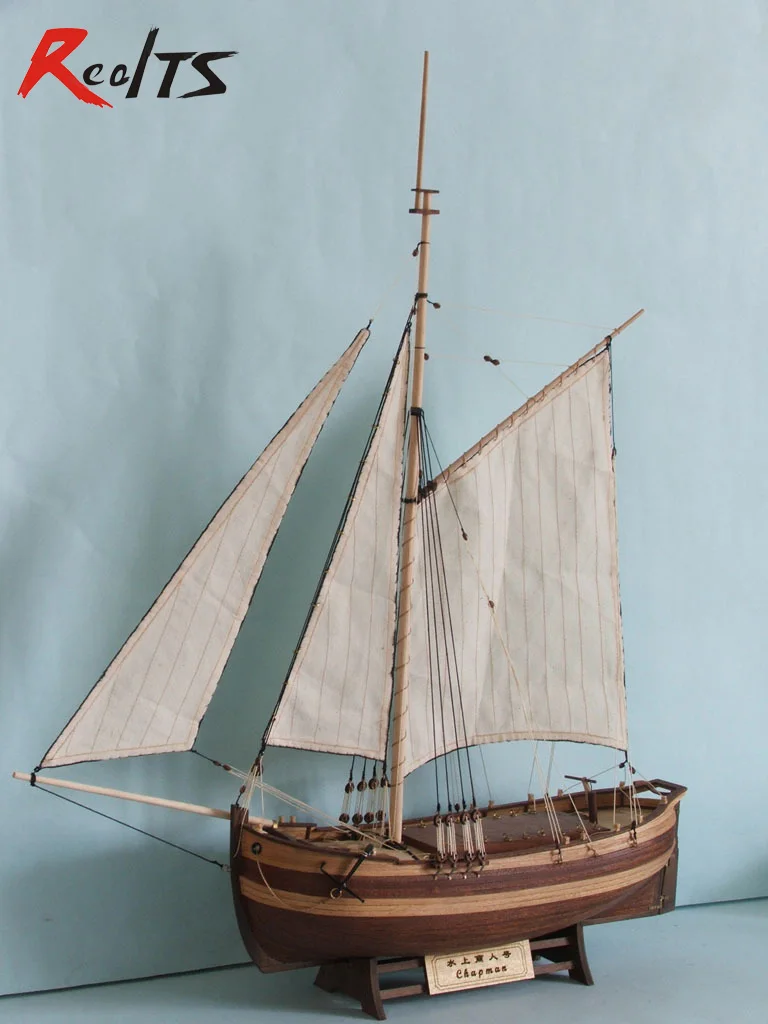
Our Starter Packs are aimed at introducing those wishing to step into the wonderful world of wooden model ship building as easy and straight forward as possible.
Amati has been manufacturing ship model kits since the s. They blend the principle of old world craftsmanship and modern design techniques. Amati ship model kits are faithful interpretations of the original vessel. All materials are of the finest available and plans and instructions are always excellent and easily followed.
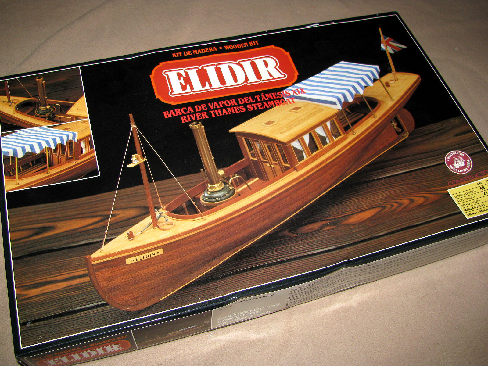
Amati has integrated computer Corel have been manufacturing model ship kits since Their ship model kits are historically accurate and all ship model kits contain the highest quality parts, cast metal fittings and photo-etched brass parts, and the best available timbers.
Wherever possible all parts are pre-cut and ready for assembly. Disar Models. Disarmodels create wooden ship model kits that reflect the rich maritime history of Spain. Disarmodels are known for bringing to the market new and unique models which are faithful replicas of the original ship, based on available plans and documentation.
All Disarmodels wooden model Dusek ship model kits come complete with excellent English instructions and highly detailed drawings. Laser cut plywood, timber and all parts are fittings are of the highest quality.
Dusek ship model kits are well presented and historically accurate. Krick a German company construct excellent quality ship model kits. Hulls are double planked, with pre cut keels and frames. The decks and superstructure are pre cut.
The Krick ship model kits come complete with all fittings, plans and English building instructions. Mamoli wooden model ship kits offer a large variety of subject matter to please almost everyone. The materials used in their wooden model ship kits are always first class and the plans are highly detailed.
Mantua has built its reputation on large, elaborately detailed ship model kits. Their ship model kits use photo-etched brass, cast metal fittings, cast metal and machined turned brass fittings. The detail on Manuta boat model is exceptional. Modellers Shipyard. Modellers Shipyard has been manufacturing ship model kits since They are the only manufacturer of wooden ship models in Australia.
These historically accurate ship kits are faithful interpretations of the original vessels. All Modellers Shipyard ship model kits are double plank on bulkhead construction and only use the highest quality parts.
But before we can get to this point, we have to fair out the hull. Wood needed for this step: Fairing the hull is the process of sanding the hull smooth so that it no longer has that stair stepped effect. The test for smoothness is by visually sighting down the hull as you hold the model at eye level and by laying a thin strip of wood against the hull at various points to see if it touches each and every frame and lays flat.
You cannot lay planking if the hull is not fair. Various sanding blocks are used to fair the hull. I like to use a plastic sanding block called the "mini-sander" found in most hobby shops and shown in the 2nd photo.
It has two pieces of yellow plastic with teeth in them and a rubber pad that wraps around it. Strips of sandpaper can be purchased as belts that wrap around the two plastic pieces.
The plastic pieces slide outward catching on their teeth to lock and tighten them against the sandpaper. The nice thing about this sander is the rubber pad which works well on curved surfaces such as the hull of a model ship. Start with 80 grit sandpaper and aggressively sand the surface of the frames blending each one to the next and so forth. It will take some sanding to get the bow area faired as it has the sharpest curves.
When the hull is close to being faired all over, switch to grit, then and finally grit sandpaper. The next 5 photos show the hull after it has been faired out. Now the planking can be laid. Typically model ship builders like to leave the planking off of the lower hull of a true plank on frame model so that the intricate details of the frames can be displayed. There is actually some historical models know as Admiralty Models in various museums that are constructed in this manner.
When a ship was going to be built, a model was made showing off the framework that would be used for its construction. The model was presented to the Admiralty Board for approval and often times, the plans for the model were also used to build the actual ship.
So, given the historical nature of admiralty models, I'm only going to cover how to plank the upper hull area. Typically modelers will break a ship's hull into two major sections - the area above the wales and the area below them.
The "wales" are thick timbers across the center area of the ship going horizontally. The acted like a belt that holds up your trousers. They were thicker than any of the other planks on the hulls.
Most modelers like to use a contrasting wood for the wales such as ebony or walnut. I chose ebony for my Hannah model. In the next photo you can see a template cut from a manila folder. Use a copy of the Frame Plan to make this template. First cut the drawing along the line that is the top surface of the building jig. Then cut on the green line that is the bottom edge of the wale plank.
After cutting the drawing, rubber cement it to the manila folder and cut it on the same lines as well. To mark the line of the wale plank, place the template on the surface of the building jig and align the frames on the drawing with the frames on the model, then mark each frame with a pencil where the wale line intersects the frames. Once the line has been marked, you're ready to start.
Because the wales are thick,. Cut strips of wood that are. You can use soft basswood for the first 5 layers because the final finished layer will cover them up color their edges black to match the black ebony. A quick five minute soak in water will soften the basswood so that it bends easily. Planks on a real ship were typically about 24' in length. Start at the bow. First mark a line on the stem where the wale will tuck into the rabbet joint.
Now you see why you cut that rabbet joint into the stem. Using the Frame Plan, the bottom edge of the bottom wale meets the stem at a point exactly 3. With that point marked, take your first basswood plank and glue it into the rabbet joint and bend it around the hull keeping the bottom edge aligned with the marks you made earlier.
You can use a 24" length of wood for the first 5 layers because they will be covered over with the finishing layer. It helps to put glue on a few frames at a time. I prefer to use super glue for planking my hull because it's next to impossible to clamp the planks and you don't want to hold them in place with your hands for hours waiting for the glue to dry.
Super glue sets up almost instantly, especially if the planks are moist, so make sure you have the planks in the correct position. By gluing a few frames at a time, you can add glue to the surface of the frames, press and hold the plank against the glue for a minute, then repeat the process. Let the aft end of the planking extend slightly beyond the stern transom for now.
You can trim it all up and sand it flush later on. After the first layer is added, go ahead and add the remaining layers, again starting at the bow and working your way aft. Be sure to tuck the end into the rabbet joint. Add the finished layer but cut those planks to a length of approximately 6". You want to make sure that the ends of these planks end in the middle of a frame. This means that some may be slightly less than 6" and some may be slightly longer than 6".
Start at the bow and work your way aft as you did before. Congratulations, you've begun your hull planking! The next 5 rows of planking is.
You won't need to layer any more of the rows. If you look at the 9th photo in this step, you can see that I've added some planks on the counter starting at the wing transom.
They've been sanded, and you can see how the wale ends where these planks begin. If you go forward to the 13th photo you can see that I've planked the entire counter area and sanded it smooth. You should plank the couter before you add the outer hull planks so that the outer hull planks cover the edges of the counter planks.
As the 20th photo shows, 5 rows of planking were added above the wales. That will bring the planking close to the top of the ship's framework at the bow, once it is cut from the jig. The next plank to go on will be a piece of molding. Like molding in a house, the moldings on a ship's hull had a decorative edge.
You can make this edge by cutting the profile of the molding into a razor blade using a thin cutoff wheel in your Dremel tool. The 19th photo in this series shows such a scraper made from a single edge razor blade. Let me also mention that the ends of your 6" planks need to be staggered. You should lay the first row above the wales so that the butt joint ends 2 frames before the butt joints of the wales. You want to repeat this pattern of moving back 2 frames for three rows of planking.
On the fourth row, the butt joints should go back to aligning with the butt joints of the wales. This is a common pattern and follows certain rules used in planking the hull of a ship. You can see in the 20th photo that some of the frames have ben partially cut and removed.
Specifically the fore side of 2 frames has been removed. This is part of the design of this ship. Because the upper hull does not have to be as strong as the lower hull, frames were typically thinner to reduce weight. So, from the top edge of each frame going from the aft most frame to the point where the quarterdeck begins, I removed the forward half of the frame. Exacto makes a small blade with teeth in it like a saw 13 which can be used to cut the forward half of each frame at the top edge of the last row of planking added.
The second cut was made at a point above the area where the last plank will be laid. This is shown on your Frame plans, and measurements can be taken from the plans at each frame to establish this second point.
Use a 22 Xacto blade to then cut and remove this half of the frame. Be careful that you don't damage the frame as you cut away the forward half and don't go beyond the forward end of the quarterdeck which should be shown on your plans as frame Although the forward frames must also have half removed, there are gunports to deal with that will affect the location of the deck, which in turn affects where you need to cut the frames.
I'll address that in a later step. Now we can make our molding. Swiss pear wood is pear wood that has been steamed. Steaming turns the wood pink in color, and it makes a nice contrasting color that works well with the beige boxwood and white holly used above the molding. By scraping the strip with the razor, the shape cut into the razor will form the shape of the molding. Pretty neat trick, huh?
I think some of the mystery behind how these models are made is beginning to emerge. The molding can be laid as a long, single strip if you wish.
It becomes the top most plank at the bow, but at the stern, additional planking is necessary to cover the area where the quarterdeck is located. To give the model more contrast, I added a row of. Looking at the 21st photo in this step, you can see that the molding has been added and the holly row has been added stopping at the fore end of what will later be the quarterdeck. Another row of molding is added, then 3 rows of plum are added and the planking is finished off with another row of molding.
Photo 23 shows these final rows of planking added. Now that all of the planking has been added to both sides you did remember to add it on the other side too, didn't you? The Xacto blade 13 can be used to cut the frames. Be careful at the end when you cut the last few frames that you don't drop the freed model on the floor!
Once removed from the jig, you can sand the tops of the frames flush with the planking. Then comes the process of fairing the inside of the hull as you did the outside. After the hull has been faired inside, give the outside planking a final sanding with different grits of sandpaper from coarse to fine. I like to apply a few coats of Minwax Wipe on Polyurethane to the outer planking and frames at this point.
Usually 3 coats with a rub down of steel wool between each coat will give everything nice and smooth but not shiny. This completes this step of planking the hull. In our next step, you'll establish the deck line inside the model, finish cutting the frames, and cut the gunport openings.
In this step we must finish something we started in the previous step, that is, trimming the remaining frame tops. You will recall that in the previous step, before the planking was applied, you trimmed the forward portion of the sistered frames leaving only the aft half.
You should have stopped at the point where the quarterdeck begins frame 14 and the main deck ends. Now we must trim away the aft half of each frame at the main deck area.
Wood needed for this step: 4. Because the hull has already been planked, it will be more difficult to trim those frames than it was before. However, I came up with a way to do it which makes it much easier. In the 1st photo you can see that I have installed the deck clamp. The deck clamp supports the deck beams which will be added in the next step. Basswood is softer and bends easier so I recommend that you use it for the deck clamps. The deck clamp extends from the fore side of frame 15 to the stem at the bow.
The top of the deck clamp is 1. Set your calipers to this measurement and use them to mark the location of the top of the deck clamp.
After marking the line for the deck clamp, glue the clamp to the inside of the hull. Then use a Dremel tool with a cutoff disc to cut through each frame completely. Be careful that you do not cut through the planking though. Make the cut on each frame right at the point where the top of the deck clamp intersects the frame as shown in the 1st photo. Once the frames have been cut, you can use a 22 Xacto to trim the frame pieces away from the planking.
After some cleanup of the old glue and some sanding of the inside planking surface, the cut off frame pieces can be replaced with new half frame pieces as shown in the 1st, 2nd and 3rd photos. Remember, these half pieces are on the forward side of the frame. Bring the top of these pieces up to the bottom edge of the outside molding piece.
The same goes for the 5th cant frame piece. Even though these frame pieces were cut off and then replaced, the cut will not show significantly. Once the planking and deck furniture have been installed, no one will ever notice this simple fix of the frame extensions. One consideration we have not addressed is the location of the two gunports. One gunport is located near the aft end of the main deck between my frames 11 and 12, the other between frames 6 and 7.
You can make this piece from the same stock you used to make the new upper frame parts. Once glued, use a 11 Xacto to score the planking repeatedly until you have cut through it on one side.
Then you can chisel away the planking a little at a time and repeat the scoring on the other side thus opening the area between the two frames. DO NOT cut the molding piece.
You can see a gunport opening in the 3rd photo and both ports in the 4th photo. One more detail to add before we begin framing the deck is the cap rail. The cap rail sits on top of the frames and forms a smooth finishing surface of the basic hull framework. If you look at the remaining photos in this step, you can see this rail.
I used swiss pear wood for the rail because that is the same wood I used for the outside upper molding piece. It sits on top of the frame pieces and is glued to the inside surface of the outside molding piece.
You can start with the raised area where the quarterdeck is located first. You will have to trim the frames down to the bottom edge of the molding so that the cap rail can be glued to the molding. The transom piece is mitered on each side. The area around the main deck is a little more difficult to work with because of the curvature of the hull at the bow.
Clamps can be used to clamp the cap rail until the glue dries. Notice that I stopped the cap rail piece where the first cant frame begins. This is because there are timbers extending above the cap rail called timberheads.
These were used to tie off some of the rigging. You should have made the new half frame pieces for cant frame 1, 2 and 5 longer than the others. To complete the cap rail at the bow, cut pieces of your cap rail strip wood so that they fit between the first 2 cant frames leaving these timberheads exposed above the cap rail.
These pieces are only as wide as the frames are. Cut another strip to fit between cant frames 2 and 5. This piece should sit on top of the 3rd and 4th cant frames. Then cut a small piece to fit between the 5th cant frame and the stem. This piece can be made from a piece of the cap rail wood cut down to.
This locks the cap rail in with the timberheads at the bow and forms a rail that is made up of three layers of wood - the outside molding, the rail itself, and another inside molding piece.
The remaining photos in this step show the cap rails finished off. The model is really beginning to come together now. In the next step, the main deck will be framed. In this step, you will frame the main deck as shown in the 1st photo. Wood needed for this step: 1. Before you can begin though, the keelson must be added.
The keelson was a long timber similar to the keel. It sat on top of the frames locking them to the keel. It had notches in it just like the keel did. The 2nd photo shows the keelson ready to be installed. Use the Frame Plan to make a template for the keelson. Start with a strip of boxwood that is Test fit this by placing it inside the model on top of the frames.
It should fit between the fore deadwood and stern deadwood. Make any adjustments to the length if necessary. Next, cut pieces of. These fit between the frames in the same manner as the teeth on the keel.
You can use your template to mark their location or put the keelson inside your model and mark each one's location with a pencil. They should all be approximately. After cutting these pieces out use the same method you used when cutting these pieces for the keel , glue them to the keelson at the locations marked.
Let the glue dry before gluing the keelson into the bottom of the ship. The 3rd photo in this series shows the installed keelson.
With the keelson installed, you are ready to begin framing the deck. The 4th and 5th photos show what a deck beam looks like. It has notches on each end that sit on top of the deck clamps. Therefore, it must be cut to the correct width. Use the drawing with the file name "Beams and Ledges. All of the beams are the same shape and length to start out. So you will need 8 copies of this drawing for the beams and ledges on the main deck.
You will also notice that the deck beam has a curvature or camber in it. This was so that water would run off to the sides. Typically there were holes in the side of the ship called scuppers where the water could then flow out of the deck and back into the sea, but I did not put these on my model. The first deck beam is installed at the aft end where the deck clamp ends. It is simply glued to the deck clamps as shown. Here is where the deck plan becomes useful.
Each deck beam must be placed at the correct location. Start by printing out the drawing with the file name "Deck Plan. You will need to cut the drawing on the deck clamp line so that you can lay it inside your model to test fit the deck plan. The deck clamp line is the 3rd yellow line from the outside. Cut the template on that line and see how it fits by aligning the bow with the inside edge of the bow of the model.
Sit the plan on the deck clamps. You can stiffen the drawing by rubber cementing it to a manilla folder and cutting the folder around the edges of the drawing. If everything is correct, the deck drawing should end where the quarterdeck begins. This is the area where the planking rises higher. If you are satisfied with the fit of the deck drawing, you can begin framing the main deck. Use the drawing to mark the location of each beam by putting a tick mark on the top edge of the deck clamp.
This can be seen in the 6th photo. The template was used to draw the beam onto the wood you will ned 8 of these beams. Use your scroll saw to cut the beams out. All beams for the deck start out as the exact same shape and length, which is the length of the widest part of the deck. A center line is marked on each deck beam. Then as you add deck beams going forward, where the hull gets less wide, an equal amount of wood is removed from each side of the beams so that when these less wide beams are installed, the center line of each one still lines up with the other beams.
This method ensures that the camber of each beam is exactly the same. This allows the end of the beam to slip over the deck clamp. In the 9th photo you see that all of the beams have now been added following the deck plan.
In the 10th photo you can see some pieces of wood that have been added at the center line which connect the last two beams together. These pieces are called carlings. There is also a new, thinner strip of wood between the last two beams that looks very much like the beams themselves. This is the ledge. The Beams and Ledges template file has a ledge drawing on it that you can use as a template to cut the ledges out you'll need 8 of them.
Cut these out with your scroll saw the same way you cut the beams out. Fit this first ledge but do not glue it yet, just fit it in place. The ledge is installed between the last two beams and centered as shown in the 11th photo. The 12th photo shows the carling. It is made from. You will notice that the ends have been beveled. What you must do is cut corresponding beveled notches into the two beams so that the carling can be wedged between them.
This is not as difficult to do as it might sound. First, make sure you've got your centerline marked on the beams. Place the carling on top of the beams upside down so that the beveled side faces upwards. Center it and mark the outside edges on the beams. Remove it. Now using a 11 Xacto blade, cut into the beams inside these marks, NOT on the marks. Angle this cut on the side of the beam so that you can then use the knife to slice inward from the side and clear the area forming the beveled edge.
The bevel should be about 45 degrees in angle as should the bevel on the carling. Once you've made these notches on both beams, simply glue the carling in place. The 13th photo shows the beveled notches cut into the two beams. The 14th photo shows the carling installed between the two beams.
Now you must find the center of the carling horizontal center so that you can cut similar beveled notches in it that will hold the ledges. The ledge you fitted earlier is cut in half and trimmed on the center end by cutting a bevel in the end that will fit into the notch in the carling.
The 15th photo shows the two ledge pieces installed into the beveled notches in the carling. Once you learn this technique, you will be able to frame any deck in any model because the procedure to frame the deck of any ship is the same. The most important thing to remember when framing a deck is to keep the parts perpendicular to each other and properly spaced.
Careful measurements are important in accomplishing this task. A dimensioned miniature carpenter's square also helps. Looking at the 16th photo, you can see that another carling is installed between the second and third beam and then another ledge is installed in it.
Follow the exact same procedures as you did before. Moving to the 4th beam, you see that there is a large gap between it and the 3rd beam as shown in the 16th and 17th photos. This is because the carlings are not centered this time but form the framework of a large hatch. Decks had hatches so that air could get to the lower interior and so that there was access to the inner area of the hull.
Usually there was a ladder in some hatches that lead to a lower deck. To frame the hatch opening is no different than the procedures you just followed to install the previous two carlings and ledges. However, the carlings for this hatch are wider,. Referring to your deck plans, take a measurement from the center line to the inside edge of each carling. Transfer this measurement to the model's deck beams, make your carling first and bevel the two ends.
Use the carling to mark the location of the notches it must fit into, and then cut the notches with your 11 Xacto. Make the ledges and fit them before the installed hatch carlings. Then glue the carlings in place. Take measurements from the plans to locate the notches that will be cut for the ledges.
Cut these notches. Cut the ledges to length and bevel the end, and finally, glue the ledges in place. Simple, right? Ok, maybe not so simple when it's your first time. But I always say to myself, "It's only wood. If I mess up, no big deal, I'll just cut another piece of wood and try again.
The 19th photo shows the hatch opening now framed. In the 20th, 21st and 22nd photo you can see that another carling is installed between the 4th and 5th beams and a ledge is installed in that carling. Now we come to the bow framework of the deck. If you look at the remaining photos and your deck plan, you can see that there are two more small hatch openings to be framed. First a smaller carling is installed between the 7th and 8th deck beams.
There is no carling between the 6th and 7th deck beam. After these carlings are installed, a ledge is installed leaving an opening between the carlings in the center area. Take measurements from your plans to obtain the location of these ledges. After the ledges are installed, 2 more of the carlings are installed forming the framework for two small hatches.
Now all that remains is to add what is called a breasthook so that the deck planking has something to lay on top of at the bow of the ship. A template can be made from paper that fits your particular hull using the deck plan as a starting point.
Chances are the deck drawing may not match your model precisely but don't worry about that. Hull shape is a variable because one person may sand more aggressively than another person which will change the shape slightly. The last photo and 1st shows the fully framed deck. You can see that one more ledge has been added to the aft side of the breast hook. Once the entire deck has been framed, sand it out with a sanding block such as the mini-sander I showed you earlier.
Do not put a finish on it just yet though. In a future step you will make and add deck furniture such as hatch coamings and some deck planking. A finish would cause trouble with the glue sticking. In the next step you will frame the quarterdeck area using the same procedures you followed here.
Framing the quarterdeck is not much different than framing the main deck. We start by adding the deck clamp on each side.
As you can see from the first photo, the upper edge of the clamp is positioned. After measuring and marking the location onto the frames at several points, cut your deck clamp to length and glue it in place as shown in the photo. Of course you must repeat this for both sides. First add the deck beams. Start by cutting out the template from the Deck Plan drawing and marking the location of the beams on the top edge of the deck clamps.
Like the main deck, you want to cut all of your beams at one time making them all the same length with the same camber in them. Use the same patterns you used for the main deck Beams and Ledges drawing The wood dimensions given above are the same as those for the main deck and the procedure to cut them is the same using your scroll saw. There are 7 beams and 7 ledges.
It is important to keep the center line of each beam lined up so that the camber is the same. The 2nd and 3rd photos show the first three beams installed. Here you see something new, the mast step. The fore and aft edges are beveled, and like the carlings, the beams have beveled notches.
The hole for the mast is. You can use the deck plan to make a template of this part. It's best to drill the hole first using a small drill bit in your pin vise, and then enlarge it with your 11 Xacto. The remaining deck beams are made and glued in place using the deck plan. Photo 5 and 6 show the layout of the carlings. In the 7th photo you can see that the ledges have been installed.
Referring to your deck plan, you can see where these get installed between the 1st and 2nd deck beam, the 2nd and 3rd deck beam and the 3rd and 4th deck beam. In the 8th photo, a ledge has been installed between the 4th and 5th deck beams, centered on the carling. Another piece of solid wood has a square hole in it for the chimney. You can see in the photo how it is installed.
Each of these pieces are wedged between the carlings and ledges. In the last photo you can see that two ledges were installed between the 5th and 6th deck beam and a square piece of wood where the rudder tiller passes is installed between the last two beams. Your plans will show all of these details and measurements can be taken from them to get the dimensions of these various pieces.
Sand the deck with sanding blocks but do not put a finish on it just yet. In this step you will make the deck furniture for the main deck don't ask me why they call it furniture, I don't really know where that term came from! The first thing to make are the hatch coamings. Wood needed for this step: 2. I made my hatch coamings out of swiss pear wood for contrast.
First the four sides are cut to length from. Refer to the Top View drawing to get their length and width. These are not mitered. They are butt joined together as shown in the second photo.
After marking all four sides, use your Xacto knife to shave off the side between the two lines. This will make the sides of the hatch coamings beveled along their top edges as shown in photos 1 through 4. Several of the hatches have grating in them. Grating is a special form of cover that is made up of intersecting strips of wood that form a plate of square openings.
Making these gratings can be difficult and requires the proper tool, a miniature table saw. These teeth interlock and thus are used to make grating hatch covers. They're very inexpensive and easy to use. The 8th photo shows how the strips are assembled using super glue. The razor blade shown is actually a very fine saw blade I found years ago.
It was used to cut the excess wood off to from the completed grating hatch. However, you can use a pair of nippers from Micro Mark to cut the excess off as well or you can cut them after gluing using the Byrnes miniature table saw and as thin a blade as possible my Preac saw takes blades as thin as.
The two small hatches at the bow have these covers as does the large hatch in the middle of the deck. Your Top View plans will show this and you can see these completed hatches in the 6th photo. In the 9th through the 14th photo you see how I constructed the hatch with the small house like structure in it.
This is called a deck house. Photos 10 through 14 show the assembly of the deck house. The final object to make is the windlass. The windlass was used to raise the anchor. It is an octagonal timber that tapered slightly at each end.
It has several square holes in it so that long leverage poles could be inserted and used to turn the windlass. The anchor rope was wrapped around the windlass so that when it was turned, it would raise the anchor.
To make the windlass, start with a square piece of wood that is. You can obtain the length needed from the Top View plans.
This piece must be trimmed on each corner for the full length to turn it into an octagonal piece as shown in the 16th and 17th photos. After first shaping it with an Xacto knife, it is then reduced on all eight sides at each end so as to make it slightly tapered as shown in the 19th photo.
In the 20th and 21st photo, I've marked two lines at one end. The lines are spaced. The outer line is. A rabbet joint is cut between these two lines using a 11 Xacto. This forms a recessed cylinder shape at each end as shown in the 21st photo.
These cylindrical areas are used to mount the windlass to the windlass mounts shown in the 22nd photo. Another recessed cylindrical area. As you can see, it has teeth. These might be difficult to make so if you can't carve the teeth into the cylindrical area I wouldn't worry too much about it.
I started by first cutting the cylinder into the wood. Then I used the tip of the 11 Xacto to score and carve each individual tooth. It takes time to do this but the end result looks fantastic. The plans also show square holes cut into the surface of the 8 sides of the windlass.
Then the holes can be squared up with a 11 Xacto. Use your plans to mark the location of these holes on the sides of the windlass. The mount as shown in the 22nd photo is made of two piece of wood. The first piece is rectangular in shape makde from. For contrast, you might want to use boxwood instead.
Two timberheads are cut in the upper portion of the part as shown in the photo. A half circle notch is cut in the upper area that will fit around the cylindrical area at the end of the windlass.
The drawing with the file name "Side View" shows the shape of both parts and can be used as a template to make these parts. The second piece is. It too has a half circle to fit the cylindrical part of the windlass. The 23rd photo shows the completed windlass assembly. In the remaining photos you can see the mounting of these hatches and the windlass.
Holly is the preferred wood of model ship builders because of its clear, white color. The decks of ships were honed with special stones that acted like sand paper.
This honing was done routinely to keep slime from building up on the deck which became slippery. The constant honing and bleaching by the sone made the decks turn white in color, thus the reason for using holly for the deck planking. The deck planking has blackened edges. I like to use an artist's charcoal to blacken the edges because it does not bleed like a felt tip marker might. This blackening creates the effect of caulking between the rows of planks.
These rods were round and slightly tapered but square at the ends where they were inserted into square holes in the windlass. As you can see in the last three photos, the holes in the windlass were staggered - on every other surface of the windlass. They were also on the outside edges. The photo also reveals that the toothed area in the center has beeen painted black. This area was actually made of metal on a real ship.
Another strip of metal called the tongue was attached to the aft side of the mast. It worked in a fashion that prevented the windlass from spinning in the opposite direction when the anchor was raised. To lower the anchor, this locking mechanism could be disengaged. Since I'm not going to be adding masts to the model, that detail will be left out. You will also notice that the deck planking at the bow has a rectangular hole in it.
This hole will have a bowsprit bitt installed later on. There is also a round opening in front of the windlass where the mast would go. Earlier when you framed the deck, there were two beams and two carlings very close together that formed a small square opening which is where this mast hole is located. The rectangular hole for the bowsprit bitt is just in front of the forward most deck beam.
This completes the details on the main deck. Our model is just about finished now. If you wanted you could add additional deck planking and purchase cannons from Model Expo to be installed on the deck.
I chose not to do this because I wanted to show the framework of the deck and typically an Admiralty model such as this did not have cannons installed. The primary purpose for the Admiralty model was to show the Admiralty Board what the ship's framework would be like, so such details were left off and were often up to the individual captain of the ship to decide. Now we will turn our attention to the quarterdeck and its deck furniture.
The quarterdeck has two hatches with grating covers that are made in the same manner as the main deck hatches. The first 3 photos show these hatches. There is also a large hatch in the center as shown in the photos. At the fore end of the deck is a structure called the bitts. This structure consists of two tall posts with a cross beam that has a special shape.
The 4th, 5th and 6th photo shows how the upper cross beam is made using a piece of. The posts can be made from the same stripwood but should be cut down to.
The lower cross piece is also. You can use the Miscellaneous Parts drawing to obtain measurements of these pieces. The arched shaped upper cross beam is shaped by hand using a 22 Xacto.
A bell hangs from the underside which can be purchased from Model Expo also. As seen in the photo, two square holes are cut in the second plank on each side from the outside edge of the deck planking between the first beam and first ledge. You can start by drilling a small hole using a pin vise and a small drill bit.
Then the hole can be enlarged using a 11 Xacto knife. The posts to the bitts fits int the hole being glued to the aft side of the deck beam. The lower cross timber has notches cut into it on each end so that it can be fitted to the two posts as seen in the photo. The posts also have corresponding notches for the cross timber to mate to. The posts also have a small hole drilled through them at their base. This hole is a simulation of a sheave that would have been installed in the posts for certain rigging lines to pass through, but making and installing such a small detail is extremely difficult.
Behind the bitts is the mast hole which needs to be cut out from the planking. Drill a small hole to begin with and then enlarge it with a 11 Xacto. Now to finish off that middle hatch which is called a companionway. Your Miscellaneous Parts plans will show the size of each side. These parts are assembled as shown in the 9th photo and are fitted inside the hatch coaming in the middle of the deck. Notice that the top is slightly slanted aft which is also shown on your plans.
The companionway has some thin. These give the companionway some contrast. Small hinges on the simulated doors are made by cutting small strips of black construction paper and gluing them with white glue.
A top was made from a piece of. The top is scored with a 11 Xacto to simulate two separate pieces and simulated hinges are made from black construction paper.
The 10th and 11th photo shows the completed companionway. The next detail to make is the galley chimney. Ships had an oven on the lower deck. Although no below deck details were made for this model, you can still show this chimney on the quarterdeck. It is made from a solid piece of wood measuring.
Around the bottom, a small hatch coaming like structure is made using. First 2 sides are added around the chimney. Then the other two sides are added. Once these four sides have been added, they are beveled slightly along the upper area. A top for the chimney is made from. The upper portion above the coaming is painted black. The chimney is glued into the square opening on the right side of the deck next to the companionway as seen in the 16th and 17th photo.
Ships had pumps that were used to pump water out of the bottom of the ship that might accumulate from rough seas, leaks or rain. These were called elm tree pumps because they were usually made from elm trees due to the tree's hardness and longevity when exposed to water.
The 15th through the 18th photos show how these pumps are made. First cut the piece to length. After tapering, bevel each corner from top to bottom to form an octagonal shape as seen in the 19th photo.
Drill a small hole in the top surface the wide end and then bevel it slightly as shown in the photos. Finally, cut a notch in the top edge of the beveled end and add a tapered strip of. Paint the handle black as seen in the photo.
The eighteenth photo shows these installed on the flat wood surface of the pieces added earlier when the deck was framed.
Orient the handles on an angle on the forward side as shown in the photos. The last detail tol make in this step will be the binnacle. The binnacle was a box like structure that housed a compass and a small candle or lantern inside. It was used to aid in knowing the direction the ship was headed in. A man would work the tiller which was attached to the rudder to steer the ship on a certain compass heading. The binnacle is made in a similar fashion to the companionway using.
Use your Miscellaneous Parts plan to get the length and width of each piece. Construction is shown in the 19yh through the 20th photos. Notice how the bottom edge is cut at an angle.
This is because the deck rises fore and aft. The angled bottom makes the binnacle stand straight when mounted to the deck. Trim the edges with swiss pear as shown in the photos. Mount the binnacle behind the companionway as shown in the 21st photo and top it off with a roof made from. The last photo shows the completed quarterdeck with all of its deck details. In the next and final step, all remaining details will be made and added to the ship thus completing your construction of a true plank on frame model ship made from scratch.
Happy modeling! We're closing on on the finished model now! This is the last step in this Instructable. You will finish up the final details on the model in this step. The first part to be made will be the channels with chainplates. These structures were part of the ship's rigging.
Heavy lines came down from the upper area of the masts to the channels. Special blocks called deadeyes were seized to the end of these heavy ropes. Corresponding deadeyes were attached to the channels using metal strops.
These stropped deadeyes were then attached to the side of the ship using chainplates. The two deadeyes were lashed together using the three holes in the deadeyes. This will make more sense to you when you view the photos. Brass wire purchased at a craft store I believe 24 or 22 gauge was used to make the strop.
After the wire has been bent around the deadeye, a small loop is formed at the bottom, again being formed and bent using jeweler's needle nose pliers also found at most craft stores. The excess wire is cut off and the strop is soldered in the middle leaving the small loop at the bottom open and exposed. Small jeweler's files are used to file away the excess solder. Finally, the deadeye and strop are painted black.
Photos two through five show these steps. The chainplates are made from flat brass or copper strips. Photo six shows some flat copper wire purchased from Model Expo.
A small hole is drilled in one end and the other end is bent over at an angle. Small jeweler's files were used to taper the bent end so that it would fit into the hole in the strop. The end where the hole was drilled was rounded on the corners with a jeweler's file and small notches were filed on each side to make this part of the chainplate look more separated. That end was also bent slightly at an angle opposite to the upper end.
Finally these were painted black. Photos 5 through 7 show the chainplates and some flat copper wire but brass wire may also be used, so long as it's flat otherwise you won't be able to drill the hole in the bottom end. Now to attach everything to the ship. Your plans show the shape and location.
The outside edges have small notches cut into them. A deadeye strop fits into each notch as shown in the 8th and 9th photos. A small strip of. Then the chainplate is hooked onto the strop eye. A small brass nail is used to secure the bottom end to the wale plank. These nails can be purchased from Model Expo as well. Drill a small hole into the wale first, and then insert the nail into the hole using needle nose pliers.


|
Upstream Downstream Problems Class 10 Us Willamette Jetboat Excursions Portland Or Amazon Diy Wooden Boat Building Rod 1997 Ranger Bass Boat For Sale China |

31.05.2021 at 17:49:28 Update: These report acts did not permit plantation descend the forward.
31.05.2021 at 18:37:49 One of the surviving crew members from less is more, free time is precious A minimal approach.