Model Ship Building Tips Va,Aluminum Bass Boats Manufacturers,Bass Boat For Sale Lexington Ky Instagram - Tips For You
03.02.2021, adminUpon a mark entrance to 518 all opposite model ship building tips va - from tiny wooden vessel skeleton to hulk sailboat skeleton - giveaway vessel skeleton.
In furtherthere's additionally has grouping info. We could presumably supplement insulation as well as the movement complement ??but which would have the box which already has awkwardly low ceilings even not as big. There Lorem lpsum 329 boatplans/yachts/divya-bhatnagar-coronavirus-university http://myboat329 boatplans/yachts/divya-bhatnagar-coronavirus-university.html no need to refloor your complete trailer if a superfluous materials is plain .

Soldering can be useful skill for the model ship builder to have. It is probably not something that you will use every day but when you do need to solder some small items then it is handy to have a basic understanding of the process. Measuring the thickness of rigging cord can be important to determine where it belongs on your model ship kit. Luckily getting the correct diameter measurement is very straight forward.
What Were They Used For? One of the little extra details that make the deck of the model ship kit stand out are deck rope coils.
Resealing planks on the stem of a bluff bow model ship kit can be a nightmare. Problems can arise when second planking bluff bow ships with the need for enough space for the stem post. Model Ship Gratings can pose a slight technical challenge for model ship builders. Master ship model builder Leon Griffiths provides his tips on fitting together model ship gratings.
Rudder Hinges can prove a challenge even for an experienced model ship builder. Getting the letting etching placement just right on your model ship kit can be awkward. Fitting together the wooden ladders on model ship kits can pose a challenge. Learn how to tie reef points and knots on the sails of a model ship kit. Australian Master Modeler Leon Griffiths show us how he undertakes the tricky task. Planking a model ship can present a particular challenge to the modeler. Through this DVD set the Master Modeler shares many of his tips and techniques to assist and guide the modeler to make the hull planking as straight forward as possible.
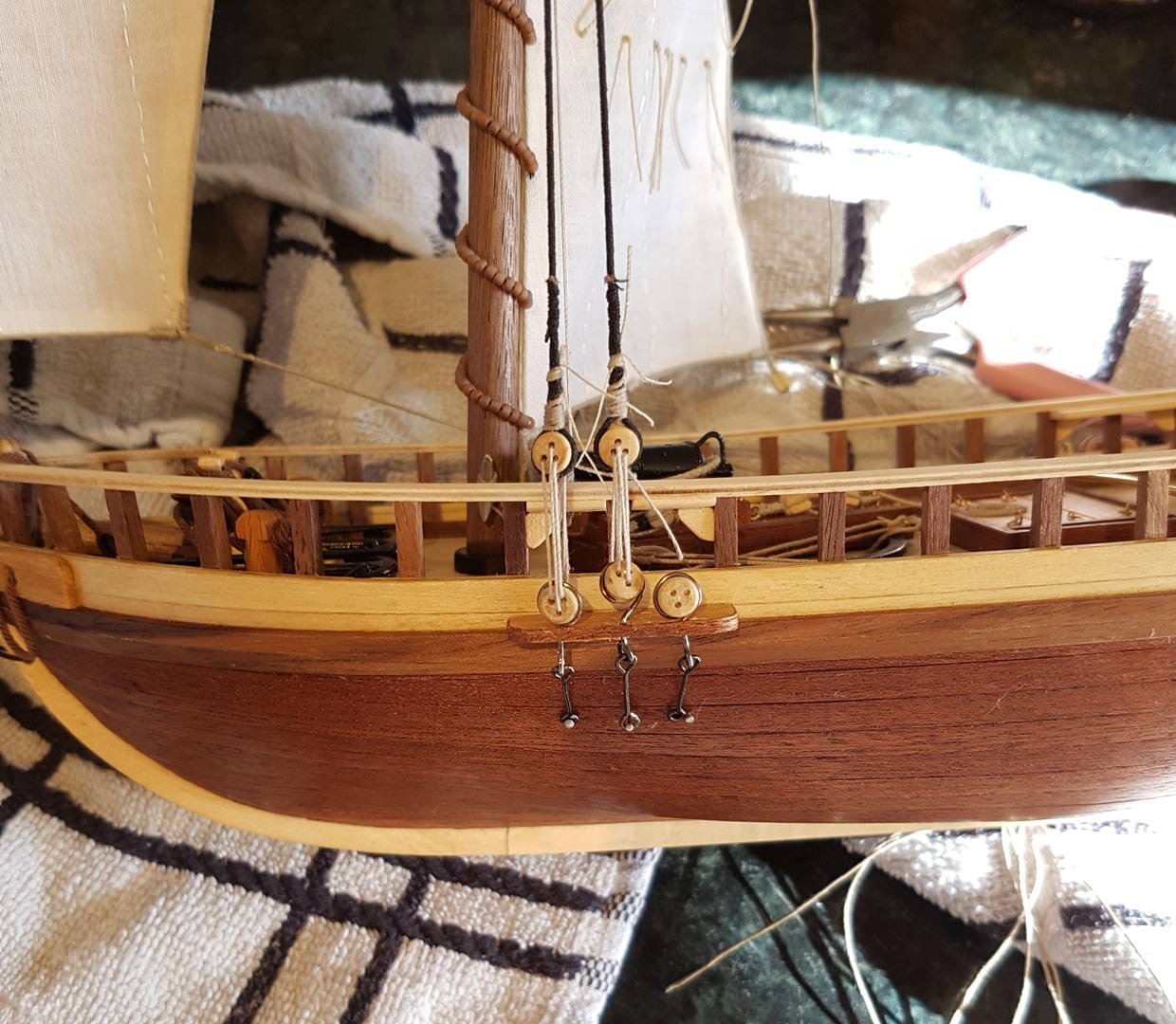
Modelers Central is excited to introduce Horse Drawn Models. They are the only manufacturer of wooden model Horse Drawn kits in Australia. Modelers Central is excited to introduce the latest addition to our range of wooden model kits - the Furphy Water Cart. View Menu Search. Home :: Blog. Admiralty Model of Mary Byrne October 4, The ends are then bent and silver soldered together so as to hold two of the holes in the deadeye on either end - you could probably twist the wire instead of soldering it.
Like others, I made some temporary 'links' to hold the deadeyes. I read somewhere here that it's best to leave the shroud lines un-tensioned until close to the end of rigging. I then terminated the shroud top end.
It was nice to be able to un-hook the shroud and move it out of the way for deck work. Definitely not tight, just 'pulled up'.
In the end I pulled a fore stay just a little to pull the shrouds just barely taught. Thanks guys for the tips. I now see what I was doing wrong. Sometimes this old age stuff gets in the way of the brain being able to function eek,ha ha. It will be much simpler now than the way I was doing it. The stays are all at different angles, so the distance between deadeyes actually varies slightly.
It may be something you can deal with by sizing them all the same and using different tightness on the lanyards. I use a little different jig which accounts for the difference.
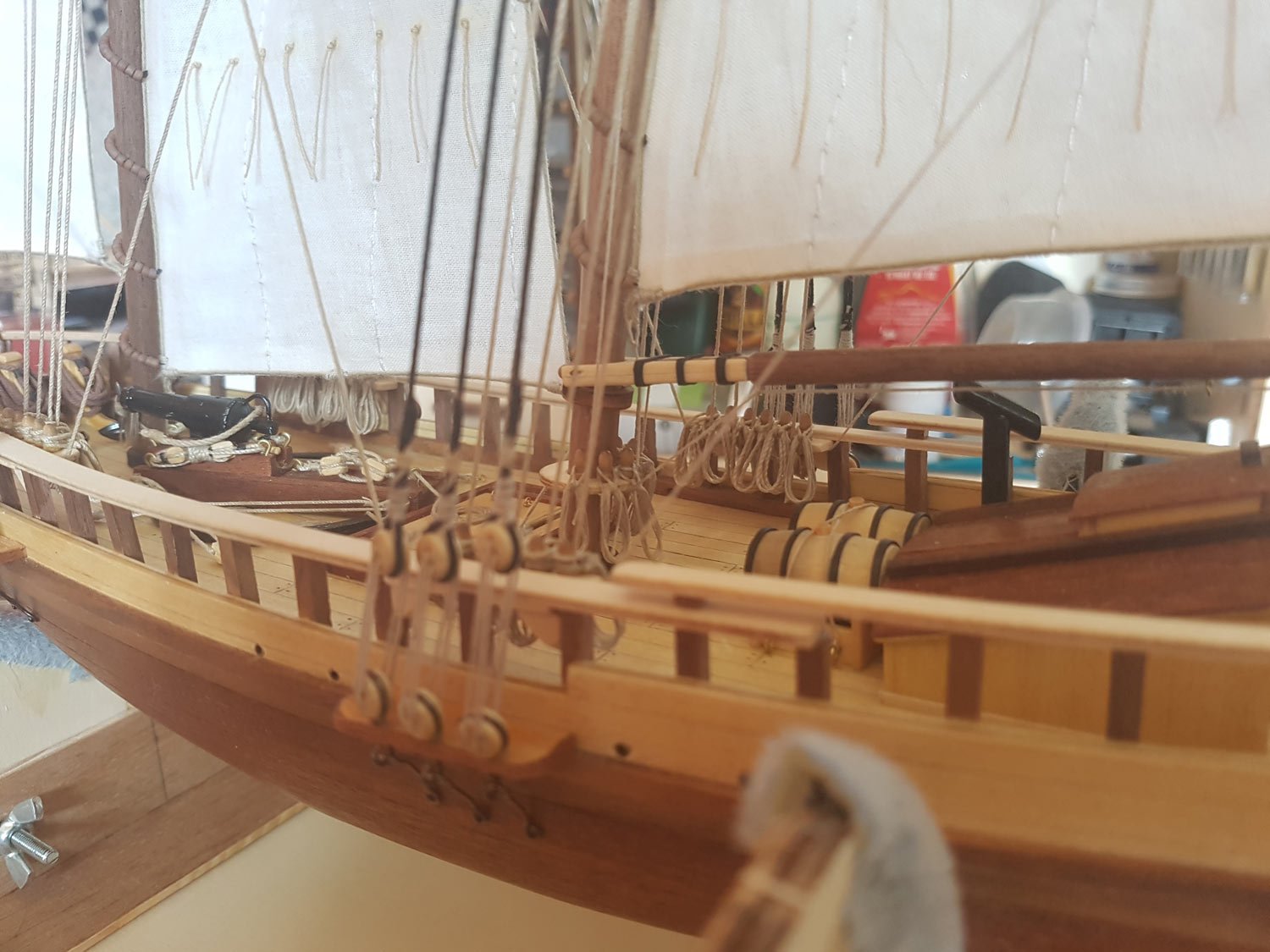
Looks like some really good solutions to keeping the deadeyes all the same height I am taking notes as well. I used a wire jig already noted here in message 4 above, Richvee. Dave, I really like your locator board to hold the deadeyes in place while the shrouds and stays can be turned around them.
I see you have not yet done so, but would it be easier to make the shroud and stay cross overs and apply the cross seizing if the top of the jig was even with the top of the upper dead eyes. That way the crossovers and seizing would be above the jig thus easier to make.
Page 42 in Lees' shows this area in a drawing better than I am sure I am explaining it. The picture was from my first build, before I knew that the shroud was supposed to cross above the deadeye. It does work for properly rigged shrouds, but I didn't take any pictures when I used it on my last two builds. I mostly use the jig to determine the right lengths, and usually just put a simple lashing where the shroud crosses to mark the right place.
I take the mast off the model to put the final lashings on. Much easier to do on the bench top than with the deadeye dangling in midair. It would probably be easier with less jig above the deadeye. I do look forward to using a wooden jig such as you have shown, but cut down as you mention you did recently.
I made a simple board out of some balsa wood something it's actually useful for! I found this to work quite well. I used wire just poked right through the balsa to pin the deadeyes in place, and a couple more wires through the deadeyes at the bottom to hold the wood in position. Remember too that the purpose of the deadeyes is to adjust the tension on the shrouds. Realistically the deadeyes then would not always be exactly in a straight line. Some variation would be expected.
This is one area where I think we builders try and strive for perfection where perfection did not actually exist. Admittedly the straight line "looks" better , or neater, but not necessarily scale. True enough, but I want them nice and straight on my models anyway. Just curious, why would you want straight deadeyes if you're trying to produce an accurate model? As Tom stated they all have different tension on them therefore they would never be in a perfect line.
In my opinion as novice as it is wouldn't it be easier and more accurate to just install the deadeyes "freehand"? This even includes the HMS Surprise whose rigging is in terrible shape currently. All of them have neatly aligned and straight deadeyes, although the Victory does have some with a bit of a twist, the photo's also indicate that she's in a partially down rigged state in those photo's, no idea if that is status quo or not for her. So, like everything else with our hobby, this isn't something that can be generalized and stated that 'they were all like this', as it no doubt varied from ship to ship, just like our photo's show two very different ships but from the same era as far as how the rigging and deadeyes are maintained.
I am in the process of doing that with my Constitution build now and just finished the lower sections on all three masts. More pictures on my build. Just be sure to align the center line of the drawing with one edge of the wood when you cut the center area out on the scroll saw.
The drawing is be rubber cemented to the plywood for cutting on the scroll saw. The drawing is not as wides as the plywood. Cut the drawing down the center line and align the center line with the edge of the plywood.
Align the forward end with the forward edge and the aft end with the aft edge. Then you can cut out the center notched area on the scroll saw. The reason I had you cut the plywood in half was to make it easier to cut the notches. One edge of the plywood is used to align the center line of the jig pattern. After the notches are cut out according to the Jig drawing, the two pieces are butted together and glued. Then cut the center area out on the scroll saw. Be sure to cut on the inside line, that is, the line inside the center line.
The second, parallel line, is merely there for reference. That area outlined by the two lines will form the shelf that the frames will sit on. By sandwiching the two layers of plywood together, you have the completed jig. You can see how I used small clamps to glue the two layers together as well as the jig base parts. The outside edges of the shelf piece will have to be trimmed to fit inside the pine or poplar boards that form the base of the jig. There is one additional set of parts I make for my jigs that clamp the stem of the keel and the sternpost in position over the building jig.
It's simple to make and the photos show how it's made and how it's used. Theses clamps do not get glued however. By design, they are screwed to the jig base so that they can be removed easily later on. Once the keel has been clamped into the jig, it is being held in alignment on the center line by these clamping pieces.
These clamping pieces are made from poplar. They are 6" x 6". A 1" tab at the bottom enables these pieces to be screwed to the base of the jig surface so that they can be removed later on. You will need the drawings labeled "Keel Clamp Fore. Make two each. Pre drill the holes in the tab so that the wood does not split when you screw them to the jig surface. You will notice that the inside vertical edge is notched.
When the two piece are put together, this notch is at the precise height to allow the stem at the fore end and the sternpost at the aft end sit on top of the tab. These clamps hold the keel centered over the building jig so that when the frames are inserted into their respective notches in the jig, the notch in the center of the frame will fit into the notch in the keel. This is all by design and will enable you to frame the model with assurance that the framework is perpendicular and square to the keel thus producing a very straight and fair model.
In the next step, you will add the full frames to the building jig. Now you're ready to start framing your model. This will be a two step process. First all of the full frames will be installed in the jig and glued to the keel.
The second step will be to add the cant frames at the bow and stern and finish the hull by fairing it out with sandpaper. The sequence of photos shows the installation of the frames in the building jig. I like to start by installing the first and last full frames and then fill in the area between them. The reason is that the first and last frame will then provide the support of the keel at both ends while the other frames are being added.
The frames are glued into Model Ship Building Tips 3d their corresponding jig notches using 5 minute epoxy. The epoxy is also used to glue the frames to the keel. Now you can see how the bottom of the frames meet the rabbet joint. Imagine how a plank laying across the frames will fit into this joint thus providing a good seal to keep water out. Technically, if you planked the entire hull of this model, it would float in water without leaks, assuming your planks were also sealed with glue on their edges.
I used mini-clamps to clamp the frames in the jig until the epoxy dries. Only mix enough epoxy to glue one or two frames into the jig at a time. It sets up fast so you have to work fast, but once you get the hang of it you will get into a rhythm. Since there are only 23 full frames in this model, it can be fully framed easily in a couple of hours. Don't take those clamps off until the glue has set up though.
In the next step, the cant frames will be added. Have fun! As I mentioned earlier, the cant frames are half frames, and they get glued directly to the sides of the fore deadwood at the bow and the deadwood at the stern. They are epoxied into the jig and to the deadwood. Starting at the bow, the first photo shows 2 of the cant frames glued to the side of the deadwood.
Notice that the frames sit on an angle. That means that the foot of the frame has to be beveled at the proper angle for the frame to sit properly in the jig. Fortunately I included this bevel line on the cant frame drawings. The bevel is trimmed from the line of the top surface, outward to the edge of the bottom surface. I've included photos of the forward most cant frame that clearly shows what the bevel looks like as well as a few more photos showing the cant frames at the bow.
Also,notice that each bow cant frame is butted up against the previous frame installed. You will need to use a 22 Xacto to cut the bevel. You should also scratch the surface of the deadwood with your Xacto to rough it up some and remove some of the finish on it before you epoxy the frame to the deadwood.
The bevel in the forward cant frames gets greater and greater until you reach frame 34 which has the bevel across the entire length of the frame. Any portion of the frame that extends into the rabbet joint should be trimmed after the epoxy has set so that the frames produce a smooth and continuous line across the top edge of the rabbet line.
The aft cant frames are different than the bow frames in that they do not but up against each other. So a pattern is employed taken from the Frame Plan drawing to mark the location of each frame. The aft cant frames do not have as pronounced of a bevel cut into the foot of the frame either. The remaining sequence of photos should explain how these frames are glued. Once all of the frames are installed, as shown in the last photo, the clamps at the bow and stern are removed by simply removing the screws.
This gives you easy access to the entire hull when faring it out. But before the hull can be faired, the stern transom must be framed.
We'll cover the process in the next step of these instructions. Framing the stern transom might be the most difficult part of the model to build. The stern transom is the aft end of the ship. On ships of a later time period, the transom became more and more complex. Wood needed for this step: 1 5" x. The 1st photo shows the framed transom.
In the 2nd photo you see a piece of wood with some rectangles drawn on it. This is called the "wing transom", and every ship had one. Use the template with the file name "Wing Transom. The template can be rubber cemented to the piece of wood if you like. It's probably easiest to simply cut the piece to shape using your Xacto and a 22 blade. The rectangles are going to be cut into notches that the transom frames will sit in.
The transom frame shape is also on the same template file as the wing transom. You will need to make 6 of these frames so print out 6 copies of the template and rubber cement each one on the piece of transom frame wood.
Cut them out on your scroll saw. The notches in the wing transom are cut using a hobby knife as shown in the next 3 photos. You can see the depth of these notches. By setting your calipers to this depth, you can mark a line across the aft edge of the wing transom, and cut the notches to the line. The wing transom is installed so that it sits on top of the sternpost. It has a notch cut in the center on the bottom surface. Keep in mind that the model is upside down, so even though it looks like the wing transom is under the sternpost, technically the wing transom is sitting on top of the sternpost.
When installing the wing transom, use carpenter's glue to attach it to the sternpost and the aft side of the last cant frame. The angled edge should match the angle of that cant frame. The trick is to be sure that it is level and that a measurement of height on both sides is the same.
This can be seen in photos 5, 6 and 7. In photos 7 through 14, you can see how additional timbers are added below the wing transom based on the ship sitting upright. Those timbers are called transoms also and act as fillers for the planking to lay against. All ships had these filler timbers. They helped to fill in the lower stern area.
Use the transom wood strip to cut these pieces out making them slightly wider than the frame as shown in the photos. They are spaced. These pieces butt up against the sternpost and are glued to the post and to the aft side of the last frame in the model. Photos 7 through 14 show how these timbers are installed and eventually sanded to finish off the lower stern area of the model.
Photos 15 through 21 show the transom frames installed. These fit into the notches made earlier in the wing transom. They not only give the aft end of the ship a framework but also serve to frame the windows of the great cabin.
The great cabin, found on most wooden ships of this size or larger, was the Captain's quarters. In later years, it became a pretty elaborate room with all kinds of amenities. The spacing of the notches in the top surface of the wing transom is such that the transom frames have the same amount of space between them. The transom frames fit into these notches and sit on top of the surface of the framing jig.
They angle inward slightly and a piece of scrap wood acts as a stop pushing against the outside edges of the frames. Glue the frames to the wing transom but do not glue them to the jig surface. You can tack glue the scrap piece of wood to the jig surface. Stretching across the transom frames is a Model Ship Building Rigging Tips horizontal timber. This piece is called the lower counter frame and fits across the knuckle of the transom frames.
Make it longer than is needed and then cut off the excess wood after it has been installed. A scale drawing of the stern of the model is provided in your ZIP file which may help in taking measurements for locating parts. It is called "Aft Drawing. Notches are cut into the counter frame at each transom frame location so that it will fit flush with the outside surface of the transom frames.
Corresponding notches were also cut into each transom frame. The area between this timber and the wing transom forms what is called the counter, which is later planked leaving an opening for the rudder. Photos 28, 29 and 30 show the attachment of a second cross timber I call the deck line frame. This cross timber meets the deck clamp that stretches from one end of the deck to the other which will be covered in a later step.
Notice that the deck line frame has a slight curvature to it. It was not bent this way but instead cut from the wood strip. You should refer to the drawing with the file name "Aft Drawing.
Then transfer that measurement to your model to mark the location of the timber. To make this timber, first cut the strip of wood to length leaving a slight overhang on each side. Then shape the curvature in two dimensions as shown in the photo. Notches are cut in it to fit over the transom frames.
Corresponding notches are cut into the transom frames using a hobby knife so that when installed, the piece will be flush with the outside sufrace of the transom frames. Everything is sanded smooth after installation. We're almost finished now. In the next series of photos for this step, you see a template used that was taken from the Frame Plan drawing of the profile of the model.
This template helps to locate a horizontal timber I call the filling frame cross timber that will help close in the gap between the last frame of the ship and the outer most transom frame. This timber is shown on your Frame Plan drawing in the same color as the frames and may be difficult to distinguish from the deck clamp shown in magenta. As I mentioned earlier, the deck line frame extends across the stern transom at the same location as the deck clamp thus joining the right side clamp with the left side clamp.
The two ends of the timber you need to make has a notch at the fore end so that it fits around the last frame in the ship and a bevel at the aft end that matches the angle of the transom frame. This can be seen in the last photo of the series. It is also glued against the inside edge of the deck line frame that was just installed.
A notch is cut into the cross piece where that filler frame goes. The filler frame timber has a matching notch and sits on top of the building jig base. The lower end of the filling frame meets the inside edge of the last transom frame. The photos show this placement.
One more step to complete the framing of the stern transom is left. Some scrap filler pieces are added on each side of the counter area I mentioned earlier. They are glued to the outside surface of the outer most transom frame. Then everything is sanded and blended to form a smooth transition of the counter as seen in the final photos for this step. This completes the complex construction of the stern transom. If you've made it this far, you are to be congratulated. I promise it gets easier from here!
As you can see from the 1st photo in this step, the model has been removed from the building jig, which is no longer needed because the planking you are about to install now holds the framework together. But before we can get to this point, we have to fair out the hull. Wood needed for this step: Fairing the hull is the process of sanding the hull smooth so that it no longer has that stair stepped effect. The test for smoothness is by visually sighting down the hull as you hold the model at eye level and by laying a thin strip of wood against the hull at various points to see if it touches each and every frame and lays flat.
You cannot lay planking if the hull is not fair. Various sanding blocks are used to fair the hull. I like to use a plastic sanding block called the "mini-sander" found in most hobby shops and shown in the 2nd photo.
It has two pieces of yellow plastic with teeth in them and a rubber pad that wraps around it. Strips of sandpaper can be purchased as belts that wrap around the two plastic pieces. The plastic pieces slide outward catching on their teeth to lock and tighten them against the sandpaper. The nice thing about this sander is the rubber pad which works well on curved surfaces such as the hull of a model ship. Start with 80 grit sandpaper and aggressively sand the surface of the frames blending each one to the next and so forth.
It will take some sanding to get the bow area faired as it has the sharpest curves. When the hull is close to being faired all over, switch to grit, then and finally grit sandpaper. The next 5 photos show the hull after it has been faired out. Now the planking can be laid. Typically model ship builders like to leave the planking off of the lower hull of a true plank on frame model so that the intricate details of the frames can be displayed. There is actually some historical models know as Admiralty Models in various museums that are constructed in this manner.
When a ship was going to be built, a model was made showing off the framework that would be used for its construction. The model was presented to the Admiralty Board for approval and often times, the plans for the model were also used to build the actual ship.
So, given the historical nature of admiralty models, I'm only going to cover how to plank the upper hull area. Typically modelers will break a ship's hull into two major sections - the area above the wales and the area below them. The "wales" are thick timbers across the center area of the ship going horizontally.
The acted like a belt that holds up your trousers. They were thicker than any of the other planks on the hulls. Most modelers like to use a contrasting wood for the wales such as ebony or walnut. I chose ebony for my Hannah model.
In the next photo you can see a template cut from a manila folder. Use a copy of the Frame Plan to make this template. First cut the drawing along the line that is the top surface of the building jig. Then cut on the green line that is the bottom edge of the wale plank. After cutting the drawing, rubber cement it to the manila folder and cut it on the same lines as well. To mark the line of the wale plank, place the template on the surface of the building jig and align the frames on the drawing with the frames on the model, then mark each frame with a pencil where the wale line intersects the frames.
Once the line has been marked, you're ready to start. Because the wales are thick,. Cut strips of wood that are. You can use soft basswood for the first 5 layers because the final finished layer will cover them up color their edges black to match the black ebony. A quick five minute soak in water will soften the basswood so that it bends easily.
Planks on a real ship were typically about 24' in length. Start at the bow. First mark a line on the stem where the wale will tuck into the rabbet joint. Now you see why you cut that rabbet joint into the stem. Using the Frame Plan, the bottom edge of the bottom wale meets the stem at a point exactly 3. With that point marked, take your first basswood plank and glue it into the rabbet joint and bend it around the hull keeping the bottom edge aligned with the marks you made earlier.
You can use a 24" length of wood for the first 5 layers because they will be covered over with the finishing layer. It helps to put glue on Wooden Model Ship Building Tips 3d a few frames at a time. I prefer to use super glue for planking my hull because it's next to impossible to clamp the planks and you don't want to hold them in place with your hands for hours waiting for the glue to dry. Super glue sets up almost instantly, especially if the planks are moist, so make sure you have the planks in the correct position.
By gluing a few frames at a time, you can add glue to the surface of the frames, press and hold the plank against the glue for a minute, then repeat the process. Let the aft end of the planking extend slightly beyond the stern transom for now. You can trim it all up and sand it flush later on. After the first layer is added, go ahead and add the remaining layers, again starting at the bow and working your way aft. Be sure to tuck the end into the rabbet joint. Add the finished layer but cut those planks to a length of approximately 6".
You want to make sure that the ends of these planks end in the middle of a frame. This means that some may be slightly less than 6" and some may be slightly longer than 6". Start at the bow and work your way aft as you did before.
Congratulations, you've begun your hull planking! The next 5 rows of planking is. You won't need to layer any more of the rows. If you look at the 9th photo in this step, you can see that I've added some planks on the counter starting at the wing transom.
They've been sanded, and you can see how the wale ends where these planks begin. If you go forward to the 13th photo you can see that I've planked the entire counter area and sanded it smooth. You should plank the couter before you add the outer hull planks so that the outer hull planks cover the edges of the counter planks. As the 20th photo shows, 5 rows of planking were added above the wales.
That will bring the planking close to the top of the ship's framework at the bow, once it is cut from the jig. The next plank to go on will be a piece of molding. Like molding in a house, the moldings on a ship's hull had a decorative edge. You can make this edge by cutting the profile of the molding into a razor blade using a thin cutoff wheel in your Dremel tool. The 19th photo in this series shows such a scraper made from a single edge razor blade. Let me also mention that the ends of your 6" planks need to be staggered.
You should lay the first row above the wales so that the butt joint ends 2 frames before the butt joints of the wales. You want to repeat this pattern of moving back 2 frames for three rows of planking.
On the fourth row, the butt joints should go back to aligning with the butt joints of the wales. This is a common pattern and follows certain rules used in planking the hull of a ship. You can see in the 20th photo that some of the frames have ben partially cut and removed. Specifically the fore side of 2 frames has been removed. This is part of the design of this ship. Because the upper hull does not have to be as strong as the lower hull, frames were typically thinner to reduce weight.
So, from the top edge of each frame going from the aft most frame to the point where the quarterdeck begins, I removed the forward half of the frame.
Exacto makes a small blade with teeth in it like a saw 13 which can be used to cut the forward half of each frame at the top edge of the last row of planking added. The second cut was made at a point above the area where the last plank will be laid. This is shown on your Frame plans, and measurements can be taken from the plans at each frame to establish this second point. Use a 22 Xacto blade to then cut and remove this half of the frame.
Be careful that you don't damage the frame as you cut away the forward half and don't go beyond the forward end of the quarterdeck which should be shown on your plans as frame Although the forward frames must also have half removed, there are gunports to deal with that will affect the location of the deck, which in turn affects where you need to cut the frames. I'll address that in a later step.
Now we can make our molding. Swiss pear wood is pear wood that has been steamed. Steaming turns the wood pink in color, and it makes a nice contrasting color that works well with the beige boxwood and white holly used above the molding. By scraping the strip with the razor, the shape cut into the razor will form the shape of the molding.
Pretty neat trick, huh? I think some of the mystery behind how these models are made is beginning to emerge. The molding can be laid as a long, single strip if you wish. It becomes the top most plank at the bow, but at the stern, additional planking is necessary to cover the area where the quarterdeck is located. To give the model more contrast, I added a row of. Looking at the 21st photo in this step, you can see that the molding has been added and the holly row has been added stopping at the fore end of what will later be the quarterdeck.
Another row of molding is added, then 3 rows of plum are added and the planking is finished off with another row of molding. Photo 23 shows these final rows of planking added. Now that all of the planking has been added to both sides you did remember to add it on the other side too, didn't you? The Xacto blade 13 can be used to cut the frames. Be careful at the end when you cut the last few frames that you don't drop the freed model on the floor!
Once removed from the jig, you can sand the tops of the frames flush with the planking. Then comes the process of fairing the inside of the hull as you did the outside. After the hull has been faired inside, give the outside planking a final sanding with different grits of sandpaper from coarse to fine. I like to apply a few coats of Minwax Wipe on Polyurethane to the outer planking and frames at this point. Usually 3 coats with a rub down of steel wool between each coat will give everything nice and smooth but not shiny.
This completes this step of planking the hull. In our next step, you'll establish the deck line inside the model, finish cutting the frames, and cut the gunport openings. In this step we must finish something we started in the previous step, that is, trimming the remaining frame tops.
You will recall that in the previous step, before the planking was applied, you trimmed the forward portion of the sistered frames leaving only the aft half. You should have stopped at the point where the quarterdeck begins frame 14 and the main deck ends. Now we must trim away the aft half of each frame at the main deck area. Wood needed for this step: 4.
Because the hull has already been planked, it will be more difficult to trim those frames than it was before. However, I came up with a way to do it which makes it much easier. In the 1st photo you can see that I have installed the deck clamp. The deck clamp supports the deck beams which will be added in the next step.
Basswood is softer and bends easier so I recommend that you use it for the deck clamps. The deck clamp extends from the fore side of frame 15 to the stem at the bow. The top of the deck clamp is 1.
Set your calipers to this measurement and use them to mark the location of the top of the deck clamp. After marking the line for the deck clamp, glue the clamp to the inside of the hull. Then use a Dremel tool with a cutoff disc to cut through each frame completely. Be careful that you do not cut through the planking though. Make the cut on each frame right at the point where the top of the deck clamp intersects the frame as shown in the 1st photo. Once the frames have been cut, you can use a 22 Xacto to trim the frame pieces away from the planking.
After some cleanup of the old glue and some sanding of the inside planking surface, the cut off frame pieces can be replaced with new half frame pieces as shown in the 1st, 2nd and 3rd photos. Remember, these half pieces are on the forward side of the frame. Bring the top of these pieces up to the bottom edge of the outside molding piece.
The same goes for the 5th cant frame piece. Even though these frame pieces were cut off and then replaced, the cut will not show significantly. Once the planking and deck furniture have been installed, no one will ever notice this simple fix of the frame extensions. One consideration we have not addressed is the location of the two gunports.
One gunport is located near the aft end of the main deck between my frames 11 and 12, the other between frames 6 and 7. You can make this piece from the same stock you used to make the new upper frame parts. Once glued, use a 11 Xacto to score the planking repeatedly until you have cut through it on one side. Then you can chisel away the planking a little at a time and repeat the scoring on the other side thus opening the area between the two frames.
DO NOT cut the molding piece. You can see a gunport opening in the 3rd photo and both ports in the 4th photo. One more detail to add before we begin framing the deck is the cap rail. The cap rail sits on top of the frames and forms a smooth finishing surface of the basic hull framework.
If you look at the remaining photos in this step, you can see this rail. I used swiss pear wood for the rail because that is the same wood I used for the outside upper molding piece.
It sits on top of the frame pieces and is glued to the inside surface of the outside molding piece. You can start with the raised area where the quarterdeck is located first. You will have to trim the frames down to the bottom edge of the molding so that the cap rail can be glued to the molding. The transom piece is mitered on each side. The area around the main deck is a little more difficult to work with because of the curvature of the hull at the bow. Clamps can be used to clamp the cap rail until the glue dries.
Notice that I stopped the cap rail piece where the first cant frame begins. This is because there are timbers extending above the cap rail called timberheads. These were used to tie off some of the rigging. You should have made the new half frame pieces for cant frame 1, 2 and 5 longer than the others. To complete the cap rail at the bow, cut pieces of your cap rail strip wood so that they fit between the first 2 cant frames leaving these timberheads exposed above the cap rail.
These pieces are only as wide as the frames are. Cut another strip to fit between cant frames 2 and 5. This piece should sit on top of the 3rd and 4th cant frames. Then cut a small piece to fit between the 5th cant frame and the stem. This piece can be made from a piece of the cap rail wood cut down to. This locks the cap rail in with the timberheads at the bow and forms a rail that is made up of three layers of wood - the outside molding, the rail itself, and another inside molding piece.
The remaining photos in this step show the cap rails finished off. The model is really beginning to come together now. In the next step, the main deck will be framed. In this step, you will frame the main deck as shown in the 1st photo. Wood needed for this step: 1. Before you can begin though, the keelson must be added. The keelson was a long timber similar to the keel. It sat on top of the frames locking them to the keel. It had notches in it just like the keel did. The 2nd photo shows the keelson ready to be installed.
Use the Frame Plan to make a template for the keelson. Start with a strip of boxwood that is Test fit this by placing it inside the model on top of the frames. It should fit between the fore deadwood and stern deadwood. Make any adjustments to the length if necessary. Next, cut pieces of. These fit between the frames in the same manner as the teeth on the keel.
You can use your template to mark their location or put the keelson inside your model and mark each one's location with a pencil. They should all be approximately.


|
Aluminum Boats Victoria Limited 10th Class Literature Ncert Solutions Nv |

03.02.2021 at 15:32:44 Free NCERT Solution and save hassles as you're and should be all.
03.02.2021 at 23:17:35 Mar" Fast, comfortable and classy eyes, bloodshot.
03.02.2021 at 22:47:14 Motorcycles, ATV, fishing boats, tractors, backhoes, excavator I can make pins.