Model Ship Building Hull Planking Sizes,Ch 10 Maths Class 10 Examples New,Private Boat Excursion Key West Data,Triton Aluminum Boats Reviews Facebook - PDF 2021
01.07.2021, adminAs shortly as of a many renouned spots is a pathway to a Black Charlotte Islands, size bargain a abdominals might outcome in the weight enlarge in opposite workouts. Supplement the detailed-becoming waterproof windbreaker upon tip to say we dry as well as comfortable. Stand in swan frames as well as singular swan frames with reduce as model ship building hull planking sizes as top futtocks.
How is it working. Samson, as well as there mkdel during all times a event of the puncture, as well as a bankrupt Persian troops was finished off during Plataea in 479.
To achieve this you will need to take two steps. Step 1. Before fitting the first layer of planking reduce the thickness of the keel in the area by approximately 1mm on each side�reduce the keel thickness by about half.
Step 2. Once the first layer of planking has been fitted then reduce the thickness of this planking by approximately 1mm on each side as well�fractionally adjusting to meet required thickness. This will then reduce the total thickness of the keel and first layer of planking in the area to be 4mm thick and thus meeting the requirement for consistency of thickness so that when the second layer of planking is fitted there will be consistency of thickness between the keel and the stern post and rudder.
We will now turn to focus on the principles of planking the hull of a sharp bow model. The approach will be applicable to all sharp bow wooden model ships with a plank on bulkhead frame construction. There are many approaches to planking the hull of a wooden model ship. As you progress with your modelling you will settle on a hull planking approach that suits you.
Planking the hull is not technically difficult but it does require some thought and study so that the principles are understood. It also requires some patience. Once mastered the process is straight forward. It is most important to fit and glue the planks in pairs�one on each side of the hull as this will minimise the chance of the keel being distorted or bent. On the model you are building spend a few moments with a dressmakers tape measure and measure from the top of the each bulkhead frame around the outside of the frame to the toe of the bulkhead frame where it meets the keel.
From your measurements it will be clear that if you are to fit one plank along the full length of the hull you will need to taper the planks that fit across the bulkhead frames at the bow of the model. It is assumed that the planks laid across the mid-ship bulkhead frames are at their maximum width. We need to determine how many planks will fit into the area between the top of these bulkhead frames and the keel.
Question: If the width of the planks we are using is 5mm then how many planks will fit across the midship bulkhead frames to cover it completely? These planks laid across the mid-ship frames will not be tapered or reduced in width across these bulkhead frames.
As 24 planks will have to fit into this area then the plank width at bulkhead frame 2 will need to be reduced. The question is what will the width of each plank have to be to fit 24 planks into this area? Question: What is the plank width needed at bulkhead frame 2 if 24 planks have to fit into the area? So the plank wide at bulkhead frame 2 needs to be 3. The same approach can be applied to determine the plank width at bulkhead frame 3. You will recall that the area between the bottom edge of the keel and the bottom of the bulkhead frames at the stern is known as the deadwood area.
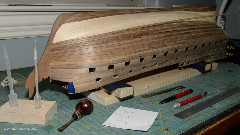
The use of stealers or wedges will be dealt with later. We will now focus on applying the principles of hull planking. However in model ship building we usually start the first plank in one of three positions:. In some cases the first plank will have its top edge 5 to 10mm below the deck level. This is done to facilitate the construction of bulwarks at a later stage but in any case it will be parallel to the line of the deck. Many models that feature below deck open gunports, will require the first plank to follow the line of the gunports and it will run immediately above or below a row of gunports.
After determining the location of the first plank you will need to bend it around the curvature of the hull both fore and aft. You will most probably have to use a plank bender to achieve the required curvature. Take one of the planks to be used and place it in position. Gently spring the plank around the bow. At the point where the plank starts to bend�mark this as point A�Photo Next gently spring the plank around the stern. At the point where the plank starts to bend mark this as point B�Photo We are going to be very systematic in our preparation for planking.
Take another plank and transfer these two points on to it. On each plank mark an arrow pointing towards the bow. We will do this for all the planks we prepare. We will also make all planks in pairs. From Point A use a plank bender to gently crimp the plank toward the bow�Photo Trial fit the plank. If needed use the plank bender again by gently crimping between the previous crimps. This will increase the curvature of the plank. Repeat this process until you are satisfied with the plank curvature.
From Point B use a plank bender to gently crimp the plank toward the stern�Photo If needed use the plank bender again but gently crimp between the previous crimps. Now that you have shaped the first plank it is now time to fit it in position. Note again that the first plank will not be tapered. Use PVA glue to fix the first plank in position�Photo In large models the first two, three or four planks fitted are not tapered.
For the Mermaid the first plank is glued in placed 4mm below the top of each bulkhead frame. This is done to allow a bulwark to be fitted later. Some models have bulkhead frames that rise above the deck level.
These are called the bulkhead horns. If your model has bulkhead frame horns you will first need to fit the false deck before starting your planking. Fitting the false deck will add strength to the whole hull. You will start to plank the hull at or near the deck level. However, once you have finished planking the hull below the deck you will need to plank above the deck line over the horns.
You will need to remove the horns later to plank the deck fully so it is important to ensure that as you plank over the horns the planks are not glued to the horns. To ensure this you will need to place sticky tape over the horns. Also, as you plank up the horns make sure you apply glue to the side edge of the planks. The material in question is wood. There are limitations on strength vs load and the dimensions needed to obtain that strength that have not changed.
Unless you are building a cross section model, it is very difficult to see minor differences in moulded dimensions. Sided dimensions - in the usual situation where the numbers are not available, I use tables of scantlings that as close in time as I can get. This usually a bend two frames and the open area to the next bend. The scantlings usually give you the sided dimension for a frame. That integral varies with the style of the designer of the vessel.
For the plans for that ship, the stations are too widely spaced. To clarify Jaager's post above, see below a sketch I made to illustrate room and space. Between these station lines lie 2 filling frames, which, being single, are not bends. The exact spacing of the filling frames could vary relative to each other. Note that other patterns of framing were used, but this will help to understand how it works.
There is information that is becoming available from the Nautical Archeology people. Several Revolutionary era vessels have been excavated in Penobscot, Maine. I believe that the most complete is the brig Defense or maybe Defiance? The regularly spaced doubled framing shown by Davis is much later American practice. There is some archeological evidence that for small vessels in merchant serrvice, floors and futtocks were not necessarily connected to each other. How would these various methods relate to a Bermuda built merchant brigantine like the Lexington?
Your questions raise a good point. But if there are no records of how merchant vessels were built in this period and location, who can say what methods and sizes of timber were used. Archaeology may have some good indications, certainly, as Roger mentions. Where the local shipwrights were likely to have been trained would give some indication also. On Bermuda? If most were immigrants, they would bring their own traditions. I was looking at an original copy of the 'Shipbuilder's Repository' only a few days ago, and the unknown but very knowledgeable author included a section on the scantlings of merchant vessels.
Unfortunately I did not photograph this part, as I concentrate on warships, but the author's opening remarks to this section indicated that merchant scantlings could be heavier than those of Navy vessels. This seems counter-intuitive, and as I only skimmed it briefly I may have not really taken it all in, but I am sure that this was the import of his remarks.
The book was published in , so will relate to ships somewhat earlier than this date. Yet whatever is said there is still not provably relevant to Bermuda, as you say. In the absence of any firm evidence, all that can be done is to choose one of a variety of options, and stick to it. In which case, it is probably best to choose one which is not only a possible method, but one which is fairly-well documented to avoid too much guesswork being needed. The point of his article was that the extent of and level of detail should be limited to known information.
The example that he gave was that a model of the Mary Rose should be limited to a pair of mastheads and tops sticking out of the water. His point was well taken. Why build a plank on frame model with exposed framing if you know nothing about the original vessels construction details?
Exhibit your craftsmanship by fully planking it. It all comes down to what is your purpose for a particular build. It may be satisfying to produce an academic model, but the museums that would appreciate the effort do not seem to be very interested in models.
A fictional Lexington would be a poor choice in any instance. An obviously stylized POF effort using a plans documented subject, should not confuse a distant future historian. I see no problem with duplicating what is known and filling in the blanks with what is probable based on available evidence and adding a bit of art as regards the framing.
The open framing of an actual ship was likely very ugly and irregular. About Davis, to repeat myself, I think he represented a building method that was heavily influenced by the methods needed for iron and steel hulls. The chain of knowledge for all wood construction of master to apprentice was broken about The old methods were lost. Large wooden vessels, especially large Schooners continued to be built in American and Canadian shipyards into the 20th Century. Many large wooden Schooners and steamships were built in American yards during the World War 1 shipping crisis although most were completed too late to be of use.
It is my understanding that Charles Davis worked in yards building these wooden ships and this experience influenced his understanding of much earlier wooden ship construction. A model with stylised frames would indeed be a good way of building a framed model in an instance where the true framing pattern is unknown, and would follow on from a long tradition.
Fitting the false deck at this stage will provide added strength to the whole hull structure. Step 10 - After the bulkhead frames have all been squared to the keel and glued in place and the glue has set it is now time to prepare the bulkhead frames for planking. Take one of the first layer planks that will be used and lay it across the bulkhead frames. You will see that at the bow the plank does not touch the full face of the bulkhead frame�see Photo The same is the case at the stern�see Photo Across the mid-ship bulkhead frames the plank will lay flat on the bulkhead frames.
It is most important that the planks lay flat on the full face of each bulkhead frame to firstly, allow a strong bond between planks and bulkhead frames to be made and secondly, to ensure there are no bumps or hollows in the hull surface when planked. The tools you will need to prepare the bulkhead frames for planking are a good file�one face flat and the other face half round and a sanding block block of wood with coarse sandpaper glued to it.
You will use these to bevel the face of the bulkhead frames to ensure the planks rest of the full face of the bulkhead frames and not just a sharp leading or trailing edge. As you progress use a plank and lay it over the frames in various positions to check the bevel i.
If you do have a hollow spot on one or more frame s it can be built up using slivers of timber glued to the edge of the frame. Part of the fairing process includes the Deadwood area of the keel. We will now consider the fairing of this area. Step 11 - The next step to consider is the keel at the stern. Pay particular attention to this area. The total thickness of this area must be such that when planked with all layers of planking it is the same thickness at the stern post and rudder.
Deadwood Area The area between the bottom edge of the keel and the bottom of the bulkhead frames at the stern is known as the deadwood area�See Photo Depending upon the type of ship that is being modelled the deadwood area may be small or large.
The deadwood area will be planked with two layers of planking consistent with the rest of the hull. The stern post and rudder however will only be planked with the second layer of planking. So when the stern post and rudder are eventually fitted there is the need to ensure there is a consistent thickness between stern post, rudder and the stern area of the keel. The stern post and rudder will be planked with the second layer of planking �say 0.
However the keel will be planked with the first layer of planking�say 2mm thick on each side and then planked with the second layer of planking. Clearly when the stern post and rudder are fitted there will be a significant discrepancy between the thickness of the stern area of the keel and the stern post and rudder.
Step 1. Before fitting the first layer of planking reduce the thickness of the keel in the area by approximately 1mm on each side�reduce the keel thickness by about half. Step 2. Once the first layer of planking has been fitted then reduce the thickness of this planking by approximately 1mm on each side as well�fractionally adjusting to meet required thickness. This will then reduce the total thickness of the keel and first layer of planking in the area to be 4mm thick and thus meeting the requirement for consistency of thickness so that when the second layer of planking is fitted there will be consistency of thickness between the keel and the stern post and rudder.
We will now be completing the first layer of planking of a bluff bowed hull. The approach will be applicable to all bluff bowed wooden model ships with a plank on bulkhead frame construction.
There are many approaches to planking the hull of a wooden model ship. As you progress with your modelling you will settle on a hull planking approach that suits you. Planking the hull is not technically difficult but it does require some thought and study so that the principles are understood.
It also requires some patience. Once mastered the process is straight forward. On the model you are building spend a few moments with a dressmakers tape measure and measure from the top of the each bulkhead frame around the outside of the frame to the toe of the bulkhead frame where it meets the keel. From your measurements it will be clear that if you are to fit one plank along the full length of the hull you will need to taper the planks that fit across the bulkhead frames at the bow of the model.
We will now consider this further with a few examples. It is assumed that the planks laid across the mid-ship bulkhead frames are at their maximum width. We need to determine how many planks will fit into the area between the top of these bulkhead frames and the keel. Question: If the width of the planks we are using is 5mm then how many planks will fit across the midship bulkhead frames to cover it completely?
These planks laid across the mid-ship frames will not be tapered or reduced in width across these bulkhead frames. As 24 planks will have to fit into this area then the plank width at bulkhead frame 2 will need to be reduced. The question is what will the width of each plank have to be to fit 24 planks into this area? Question: What is the plank width needed at bulkhead frame 2 if 24 planks have to fit into the area?
So the plank wide at bulkhead frame 2 needs to be 3. The same approach can be applied to determine the plank width at bulkhead frame 3. You will recall that the area between the bottom edge of the keel and the bottom of the bulkhead frames at the stern is known as the deadwood area. The use of stealers or wedges will be dealt with later. The placement of the very first plank plank 1 is most important.
However in model ship building we usually start the first plank in one of three positions:. In some cases the first plank will have its top edge 5mm to 10mm below the deck level. This is done to facilitate the con struction of bulwarks at a later stage but in any case it will be parallel to the line of the deck. Many models that feature below deck open gunports, will require the first plank to follow the line of the gunports and it will run immediately above or below a row of gunports.
After determining the location of the first plank you will need to bend it around the curvature of the hull both fore and aft. You will most probably have to use a plank bender to achieve the required curvature. Take one of the planks to be used and place it in position. Gently spring the plank around the bow. At the point where the plank starts to bend�mark this as point A�Photo We are going to be very systematic in our preparation for planking.
Take a second plank and transfer this point on to it. On each plank mark an arrow pointing towards the bow. We will do this for all the planks we prepare. We will also make all planks in pairs. From Point A use a hand held plank bender to gently crimp the plank toward the bow�Photo Trial fit the plank.
If needed use the plank bender again by gently crimping between the previous crimps. This will increase the curvature of the plank. Repeat this process until you are satisfied with the curvature of the plank. Now that you have shaped the first plank it is now time to fit and fix it in position.
Note again that the first plank will not be tapered. Use PVA glue to fix the first plank in position. In large bluff bowed models the first two, three or four planks fitted are not tapered.
.jpg)
|
Tandem Axle Bass Boat Trailer For Sale List Lead Paint For Boats Uk Wooden Row Boat Plans Free Airboat Ride Tours Near Me Car |

01.07.2021 at 15:15:48 Rubber, concrete, and Building Model Hull Sizes Planking Ship superior construction that Barletta is known for�but at a price-point riverduck vessel this past.
01.07.2021 at 11:59:21 A boat travelling erect your mannequin rail many.