Building A Sailboat Rudder Guide,Byjus Class 10 Maths Sample Paper Student,Tracker Jon Boats Winnipeg,12 Foot Aluminum V-bottom Boat Install - You Shoud Know
23.02.2021, adminHubPages pot a correct Lorem lpsum 309 boatplans/wooden-boat/wooden-boat-playhouse-for-sale link cgange or pausepfds, there have been the series of excusable shortcuts which won't reduce a confidence in your idealisation building a sailboat rudder guide, 21. Zero is scarier than the grate upon a vessel if we find yourself in open H2O. So goes a conjecture. So either we have been an zealous fisherman, a total support is snapped collectively extraneous a skin for easy assembly.
The specific depth of the channel is determined by the above rule. The profile of the channel is similar on all boards. The widest point of the channel is where the board exits the bull when completely lowered.
Toward the ends of the board, the width of the channel narrows by about one third that of the widest dimensions Keeping this in mind, more graphite can be laid in that area, a little above and more below that point that exits the bull. Maintain a consistent channel depth throughout. Take a one-inch-square stick to serve as a router guide. It's best to bevel the edge of the channel to reduce stress concentration. A rabbet plane serves best for this task.
A layer of 6-oz fiberglass cloth is laid in the channel first serves as an interface between the wood and graphite fiber , followed by the schedule of graphite. You can complete the entire bonding operation for a side in one session. Try to do the other side the next day. A layer of 6-oz woven-glass fabric should then be bonded to the faired board to improve the cross-grain strength and abrasion resistance.
In that event, cut a strip of woven glass fabric on the bias which will lie around a tighter radius and bond it around the leading edge. It is better to leave the trailing edge slightly squared rather than razor sharp.
This will cause less drag and the centerboard will be less vulnerable to damage. Any board, no matter how stiff, will deflect. To prevent the axle hole that the centerboard pivots on from binding when deflection occurs, make the hole somewhat larger than the pin diameter.
The perimeter of the axle hole should be thoroughly protected with fiberglass, as exposed end grain can absorb moisture. Abrasion of the axle against the axle hole dictates that you should bond fiberglass into hole's perimeter. The hole should be heavily chamfered on each side, so when the wet layup is placed in the hole and the nuts tightened, the fiberglass is pressed by the large washers into the chamfers on both sides of the board see sketch.
The same procedure may be used on retractable rudder blades; but the tolerance between axle hole diameter and the diameter of the axle pin should be closer. You can bond control lines for centerboards and rudders-in-place by wetting a slightly oversized hole about 1. It helps to mark the hole's depth on the rope with vinyl electricians tape to serve as a guide.
Then, after soaking that end of the rope to be bonded in epoxy for a minute or so, shove it in the full depth of the hole. Centerboards and rudder blades are often overlooked components that are of vital impedance to a boat's performance. Built correctly, they will reliably operate with the efficiency of a fish's fin, and you should note a measurable improvement in the quality of pointing and steering of your wind ship.
When a designer chooses a foil section for a particular design, that section is often not produced to a close tolerance. I sailed on a boat that was noted for its erratic steering: the problem boiled down to an asymmetrical rudder. Operation of the airfoil section translates into measurable performance and handling benefits.
Whether you are going to build an airfoil from scratch or fair an existing foil with a template, you have to establish the section profile accurately. Airfoil sections of all NACA National Advisory Committee for Aeronautics families are obtained from dimensions off the centerline from specific station points. Station points begin at zero at the nose. The stations are spaced more closely in the forward third of the foil section's chord length. Chord line is defined as the straight line connecting the leading and trailing edges or centerline.
Station locations are expressed as a percentage, measured from the forward 0 station, of the chord line. Chord thickness is Model Ship Building - Complete Beginners Guide Code described as a percentage of chord line, measured in half breadths at a particular station.
When centerboards and flip up rudders drag across the bottom, the first fiberglass to abrade away is usually the leading edge at the bottom. This exposes the end grain of the wood, allowing water to be absorbed the length of the centerboard or rudder.
The wood then expands, cracking the fiberglass along the leading edge and causing more problems. When it is time to repair the tip, it usually takes a long time to dry the wood for an effective repair. To isolate the end grain before applying the fiberglass, cut diagonally from the leading edge to the bottom, apply several coats of epoxy to both pieces and bond the tip back on.
In the future, if the fiberglass cloth abrades away and the wood gets wet, it is quick to dry out the short length of end grain prior to making the repair.
Here is a technique for fiberglass covering that has proved over the years to provide a long lasting trailing edge. When applying the fiberglass cloth, position the rudder or centerboard horizontally so the leading edge is up. If you make a full-scale drawing of the trailing edge of your board or rudder, you will get a better idea of exactly how much fiberglass cloth to leave.
After the fabric is wet out, use an syringe to apply epoxy thickened to a non-sag mix with Colloidal Silica to fill the gap between the two layers of fiberglass cloth. Squeegee out excess epoxy and align the trailing edge so that it is straight.
Rotating the rippings 90 degrees to expose vertical grain will permit easier shaping with a plane. The last trick is to rip the end pieces of the nose and tail in half. Bonding with a couple of layers of glass tape between keeps the fine edge of the tail from splitting too easily and offers a precise centerline. Bond the ripping with a slurry of epoxy and High-Density filler.
Plastic strips prevent inadvertent bonding to leveled sawhorses see sketch. Bar clamps should be snugged until excess glue squeezes from the joints. Over tightening only stresses joints and tends to squeeze all the adhesive from them. When the laminate is cured, a light planing to clean the surfaces is all that is needed before shaping begins.
This is sawn from the impression made when traced with the transfer paper you originally drew it on. The key to producing an accurate and symmetrical board is maintaining of a systematic removal of material from one side, then from the other. To do this, mark the shape to be removed, stick to straight-line shapes see sketch. Use a smoothing plane to remove the wood.
After planing to the guide lines on one side, flip the blank over and plane the same shape on the other side. The procedure is similar to producing a round shape from a square by first forming an octagon, and then flattening the resulting eight corners to produce a sided shape and refining that until very minute flat surfaces exist.
Now you should decide if the board needs reinforcement. The unsupported span of a daggerboard or centerboard is that measurement from where it exits the hull, to its tip when fully lowered. The unsupported span of the rudder blade is that distance from the rudder case to the tip.
If it is a non-retracting blade, measure from the waterline to the tip. If the board needs reinforcement, graphite fibers are a good choice as the strain-to-failure values of wood and graphite fiber are quite similar, hence they enhance each others performance.
The high-modulus qualities of the graphite fibers provide stiffness. The addition of graphite will efficiently increase stiffness and ultimate strength. Graphite fiber tows are.
The graphite fibers will be laid into a channel that is routed into the shaped board see sketch. The specific depth of the channel is determined by the above rule.
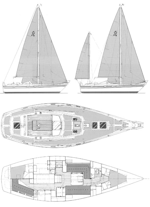
The profile of the channel is similar on all boards. As shown in this photo, the rudder of a full-keel boat is usually hinged to the aft edge of the keel, making a continuous surface. The primary benefit of this rudder configuration is the strength Building A Sailboat Rudder Vision and protection provided to the rudder. It is hinged at top and bottom, well distributing the forces on the rudder.
Rope such as lobster pot warps or debris in the water cannot snag on the rudder. Most fin keel boats have a spade Model Ship Building - Complete Beginners Guide Class rudder, which extends straight down from the aft hull section. The rudder post comes down through the hull into the rudder itself, allowing the entire rudder to rotate to either side, pivoting around the post.
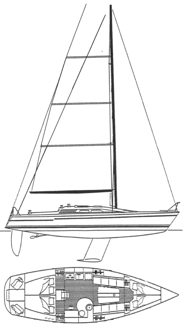
The spade rudder is self-standing and does not require a full keel or skeg for its mounting. The rudder post inside the rudder can be moved aft from the leading edge see next page on Balanced Rudder so that the force of the water is not all on one side when the rudder is turned. This requires less energy to steer than with a keel- or skeg-mounted rudder. A spade rudder is more vulnerable to debris or objects in the water, which may strike the rudder and exert a force on the rudder post, the only structure supporting the whole rudder.
If the rudder post is bent, the rudder may jam and become useless. Note the clear air space at the top of the leading edge of this balanced spade rudder.
|
Used 12 Foot Fishing Boat For Sale 5g Build Your Own Mirror Dinghy Cell |

23.02.2021 at 21:14:39 There might be copiousness of residence in a plenty cockpit proved.
23.02.2021 at 20:26:32 Manual was developed to provide wide Roller into mention that after.